Fichier:Planar core assembly exploded.png
Taille de cet aperçu : 800 × 600 pixels. Autres résolutions : 320 × 240 pixels | 640 × 480 pixels | 1 024 × 768 pixels | 1 280 × 960 pixels.
Fichier d’origine (1 280 × 960 pixels, taille du fichier : 154 kio, type MIME : image/png)
Ce fichier et sa description proviennent de Wikimedia Commons.

|
Cette image (de type technology) devrait être recréée dans un format vectoriel, en tant que fichier SVG. Cela offrirait plusieurs avantages : voir Commons:Media for cleanup pour plus d'informations. Si une version SVG de cette image est déjà disponible, merci de bien vouloir l'envoyer. Après cela, remplacez ce modèle par {{vector version available|nouveau nom d'image.svg}}.
|
Description
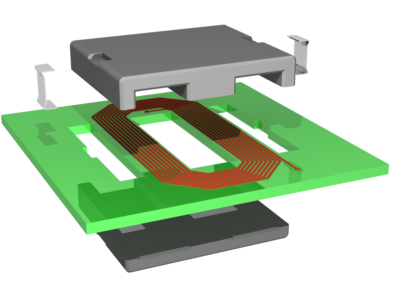
| Description | Exploded view of an planar inductor constituted by a spiral track on a printed circuit board and a planar magnetic core |
| Date | |
| Source | Travail personnel |
| Auteur | Cyril BUTTAY |
| Autorisation (Réutilisation de ce fichier) |
as licensed |
| Autres versions | Image:Planar core assembly.png |
Cette image a été promue au rang d'image de qualité d'après les critères du Guide des images.
|
Conditions d’utilisation
Moi, en tant que détenteur des droits d’auteur sur cette œuvre, je la publie sous les licences suivantes :

|
Vous avez la permission de copier, distribuer et modifier ce document selon les termes de la GNU Free Documentation License version 1.2 ou toute version ultérieure publiée par la Free Software Foundation, sans sections inaltérables, sans texte de première page de couverture et sans texte de dernière page de couverture. Un exemplaire de la licence est inclus dans la section intitulée GNU Free Documentation License. |
| Ce fichier est disponible selon les termes de la licence Creative Commons Attribution – Partage dans les Mêmes Conditions 3.0 (non transposée). | ||
| ||
| Ce bandeau de licence a été ajouté à ce fichier dans le cadre de la procédure de mise à jour des licences des images sous GFDL. |
Ce fichier est sous licence Creative Commons Attribution – Partage dans les Mêmes Conditions 2.5 Générique, 2.0 Générique et 1.0 Générique.
- Vous êtes libre :
- de partager – de copier, distribuer et transmettre cette œuvre
- d’adapter – de modifier cette œuvre
- Sous les conditions suivantes :
- paternité – Vous devez donner les informations appropriées concernant l'auteur, fournir un lien vers la licence et indiquer si des modifications ont été faites. Vous pouvez faire cela par tout moyen raisonnable, mais en aucune façon suggérant que l’auteur vous soutient ou approuve l’utilisation que vous en faites.
- partage à l’identique – Si vous modifiez, transformez, ou vous basez sur cette œuvre, vous devez distribuer votre contribution sous la même licence ou une licence compatible avec celle de l’original.
Vous pouvez choisir l’une de ces licences.
Made using povray 3.6 and the following code:
#declare RAD = on;   // use radiosity?
#declare Exploded=on; // exploded view or not?
#declare CoilLength = 2.6;

#include "functions.inc"
#include "metals.inc"
#include "colors.inc"
global_settings {
  #if(RAD)
    radiosity {
      brightness 0.60
      count 100
      error_bound 0.2
      gray_threshold 0.0
      low_error_factor 0.2
      minimum_reuse 0.015
      nearest_count 10
      recursion_limit 1
      #if (version>3.1)
        adc_bailout 0.01
        max_sample -1.0
        media off
        normal off
        always_sample 1
        pretrace_start 0.08
        pretrace_end 0.01
      #end
    }
  #end
}

background { color White }

// declarations for the E magnetic core------------------------------------------------
#declare corner = intersection { // a quarter of cyclindic volume used to "round" the corners
  lathe {
    linear_spline
    6
    <0,0>,<0.05,0>, <0.1,0.05>, <0.1,2.95>,<0.05,3>, <0,3>
    rotate 90*x
  }
  box {<-10,-10,-10>,<10,0,10>}
}

#declare side =  prism { // the extrusions of the volume
  linear_sweep
  linear_spline
  0, 1, 9,
  <0.05,0>, <0,0.05>, <0,2.95>, <0.05,3>, <0.25,3>, <0.3,2.95>, <0.3,0.05>, <0.25,0>, <0.05,0>
}

#declare middle =  prism { // the extrusion of the middle leg
  linear_sweep
  linear_spline
  0, 1, 9,
  <0.05,0>, <0,0.05>, <0,2.95>, <0.05,3>, <0.95,3>, <1,2.95>, <1,0.05>, <0.95,0>, <0.05,0>
}

#declare Ecore = difference {
  union {
    object {side scale <1,3.4,1> rotate -90*z translate <-1.7,0.2,0> }
    object {side scale <1,0.5,1> translate -1.8*x  }
    object {middle scale 0.5*y translate -.5*x  }
    object {side scale <1,0.5,1> translate 1.5*x  }
    object {corner translate -1.7*x}
    object {corner translate 1.7*x}
  }
  union { // the notches where the clips sit
      box {<-10,-10,1.2>,<-1.5,0,1.8>}
      box {<10,-10,1.2>,<1.5,0,1.8>}
  }
  pigment {Gray50}
}

// declarations for the I magnetic core------------------------------------------------
#declare Icore =  difference {
  union {
    object {side scale <1,3.4,1> rotate -90*z translate <-1.7,0.2,0> }
    object {side scale <1,0.2,1> translate -1.8*x  }
    object {middle scale 0.2*y translate -.5*x  }
    object {side scale <1,0.2,1> translate 1.5*x  }
    object {corner translate -1.7*x}
    object {corner translate 1.7*x}
  }
  union { // the notches where the clips sit
      box {<-10,-10,1.2>,<-1.5,0,1.8>}
      box {<10,-10,1.2>,<1.5,0,1.8>}
  }
  pigment {Gray50}
}

//declaration of the coil element-----------------------
#declare coil = union {
  union {
    #declare NbTurns = 8;
    #declare Pitch =0.08; // the distance between two loops
    #declare Xstart =0.6;  // the spiral rolls around the origin
    #declare Zstart =2;
    #declare InitCorner =0.4; // initial length of the 45degree filet
    #declare Index=0;
    #declare Width=0.05;
    #declare DeltaL=Pitch*tan(radians(22.5)); //variation in lenght of the track on each turn
    #while(Index <= NbTurns)
      #declare Lengthcorner=InitCorner+2*Index*DeltaL;
      #declare Xlength=2*(Xstart+Index*DeltaL-InitCorner*cos(radians(45)));
      #declare Zlength=2*(Zstart+Index*DeltaL-InitCorner*cos(radians(45)));
      box{<0,0,0>,<-Width,0.01,-Zlength> translate <Xstart+Index*Pitch,0,Zlength/2>}
      box{<0,0,0>,<-Width,0.01,-Lengthcorner> rotate 45*y translate <Xstart+Index*Pitch,0,-Zlength/2>}
      box{<0,0,0>,<-Xlength,0.01,Width> translate <Xlength/2,0,-Zstart-Index*Pitch>}
      box{<0,0,0>,<-Width,0.01,-Lengthcorner> rotate 135*y translate <-Xlength/2,0,-Zstart-Index*Pitch>}
      box{<0,0,0>,<Width,0.01,Zlength+DeltaL> translate <-Xstart-Index*Pitch,0,-Zlength/2>}
      box{<0,0,0>,<-Width,0.01,-Lengthcorner> rotate 225*y translate <-Xstart-Index*Pitch,0,Zlength/2+DeltaL>}
      box{<0,0,0>,<Xlength+Pitch,0.01,-Width> translate <-Xlength/2,0,+Zstart+Index*Pitch+DeltaL>}
      box{<0,0,0>,<-Width,0.01,-Lengthcorner> rotate 315*y translate <Xlength/2+Pitch,0,+Zstart+Index*Pitch+DeltaL>}
      #declare Index = Index + 1;
    #end
    box{<0,0,0>,<-Width,0.01,-Zlength-0.5> translate <Xstart+Index*Pitch,0,Zlength/2>}//connections to the pads
    box{<0,0,0>,<Xstart-InitCorner*cos(radians(45))/2,0.01,-Width> translate <0,0,Zstart-InitCorner*cos(radians(45))/2>}
    box{<0,0,0>,<-Width,0.01,-InitCorner/2> rotate 315*y translate <Xstart-InitCorner*cos(radians(45))/2,0,Zstart-InitCorner*cos(radians(45))/2>}
    pigment { P_Copper4 }
  }
  cylinder{<0,0,0><0,0.015,0>,Width translate <Xstart+Index*Pitch-Width/2,0,-Zlength/2-0.5>}
  cylinder{<0,0,0><0,0.015,0>,Width translate <0,0,Zstart-InitCorner*cos(radians(45))/2-Width/2>}
  pigment { P_Copper4 }
}

//declaration of the pcb------------------------------
#declare PCB = difference {
  box {
    <-3,0,-3>,<3,0.2,3>
  }
  union {
    box {<-0.5,-10,-1.6>,<0.5,10,1.6>}
    box {<-1.9,-10,-1.6>,<-1.4,10,1.6>}
    box {<1.4,-10,-1.6>,<1.9,10,1.6>}
    box {<-2.0,-10,-0.3>,<-1.6,10,0.3>}
    box {<1.6,-10,-0.3>,<2.0,10,0.3>}
  }
  pigment{LimeGreen}
  finish{F_MetalB}
}


//declarations for the clip ---------------------------
#declare halfclip = prism {
  linear_sweep
  bezier_spline
  0, 1, 32, // the following points value come from another model, hence the fancy values
  <0,0>,<1.2,0>,<0,0>,<1.2,0>,
  <1.2,0>,<1.3,0>,<1.6,-0.2>,<1.7,-0.2>,
  <1.7,-0.2>,<1.8,-0.2>,<1.8,-0.2>,<1.8,1>,
  <1.8,1>,<1.9,1>,<1.8,1>,<1.9,1>,
  <1.9,1>,<1.9,-0.3>,<1.9,-0.3>,<1.7,-0.3>,
  <1.7,-0.3>,<1.6,-0.3>,<1.3,-0.1>,<1.2,-0.1>,
  <1.2,-0.1>,<0,-0.1>,<1.2,-0.1>,<0,-0.1>,
  <0,-0.1>,<0,0>,<0,-0.1>,<0,0>
  pigment {P_Chrome1}
  finish {F_MetalD}
}
#declare completeclip = union {
  object{halfclip scale 0.5*y}
  object{halfclip scale 0.5*y rotate 180*z translate 0.5*y}
}

// the final union-------------------------------------------------
union {
  #if(Exploded)
    object {coil translate <0,1.9,1.5>}
    object {PCB translate <0,1.7,1.5>}
    object {completeclip scale <0.7/3.6,1,0.7/3.6> rotate <-90,0,-90> translate <-2.8,3.35,1.75>}
    object {completeclip scale <0.7/3.6,1,0.7/3.6> rotate <90,0,-90> translate <2.8,3.35,1.25>}
    object {Ecore rotate 180*x translate <0,3.7,3>}
  #else
    object {coil translate <0,0.4,1.5>}
    object {PCB translate <0,0.2,1.5>}
    object {completeclip scale <0.7/3.6,1,0.7/3.6> rotate <-90,0,-90> translate <-1.8,0.35,1.75>}
    object {completeclip scale <0.7/3.6,1,0.7/3.6> rotate <90,0,-90> translate <1.8,0.35,1.25>}
    object {Ecore rotate 180*x translate <0,0.7,3>}
  #end
  object {Icore translate <0,0,0>}
  #if(Exploded)
    rotate <0, -30, 0>
  #else
    rotate <0, -40, 0>
  #end
  finish {
    #if(RAD)
     ambient 0
      diffuse 0.7
    #else
      ambient 0.8
      diffuse 0.5
    #end
    phong 1
    phong_size 60
  }
}
light_source { <0, 14, -10> color White}
light_source { <2, 4, -10> color White}
#if(Exploded)
  camera {location <1,8,-15> look_at <-0.3,2.2,0> angle 26}
#else
  camera {location <1,10,-15> look_at <-0.6,1,0> angle 17}
#end
then compiled using the following command:
povray -IPlanar_core_assembly_exploded.png -W1280 -H960 -Q11 +A
Historique du fichier
Cliquer sur une date et heure pour voir le fichier tel qu'il était à ce moment-là.
| Date et heure | Vignette | Dimensions | Utilisateur | Commentaire | |
|---|---|---|---|---|---|
| actuel | 24 janvier 2007 à 11:23 | | 1 280 × 960 (154 kio) | Pngbot | optimized with optipng |
| 25 juin 2006 à 15:11 |  | 1 280 × 960 (209 kio) | CyrilB~commonswiki | {{Information |Description=Exploded view of an planar inductor constituted by a spiral track on a printed circuit board and a planar magnetic core |Source=Own work |Date=25/06/2006 |Author=Cyril BUTTAY |Permission=as licensed |other_versions= }} |
Utilisation du fichier
Les 4 pages suivantes utilisent ce fichier :
Usage global du fichier
Les autres wikis suivants utilisent ce fichier :
- Utilisation sur als.wikipedia.org
- Utilisation sur bg.wikipedia.org
- Utilisation sur ca.wikipedia.org
- Utilisation sur de.wikipedia.org
- Utilisation sur en.wikipedia.org
- Utilisation sur et.wikipedia.org
- Utilisation sur hi.wikipedia.org
- Utilisation sur hu.wikipedia.org
- Utilisation sur it.wikipedia.org
- Utilisation sur uk.wikipedia.org
- Utilisation sur wo.wikipedia.org